
Scan QR code
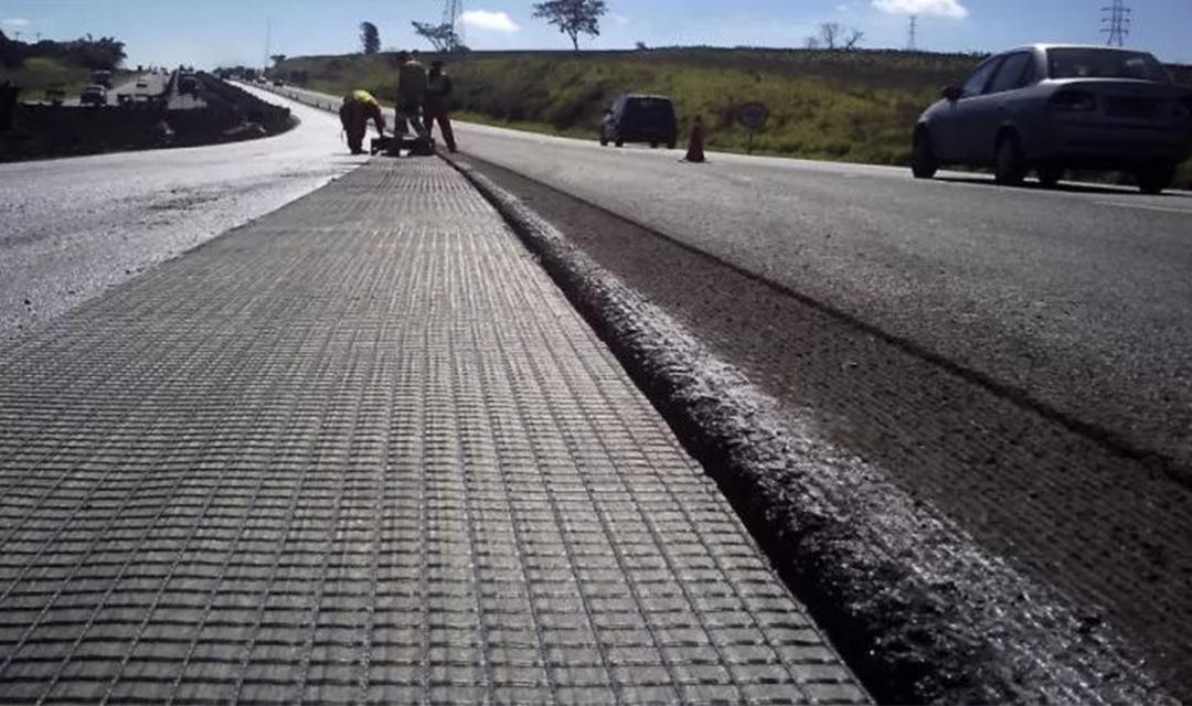
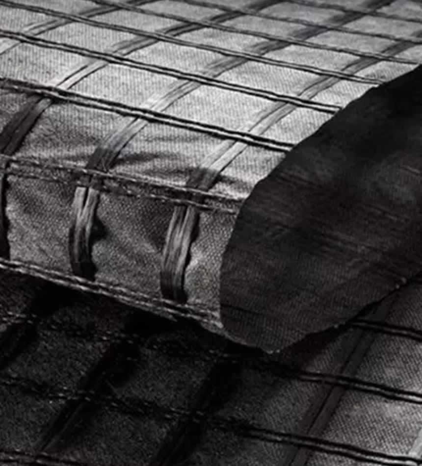
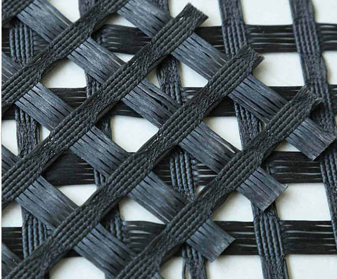
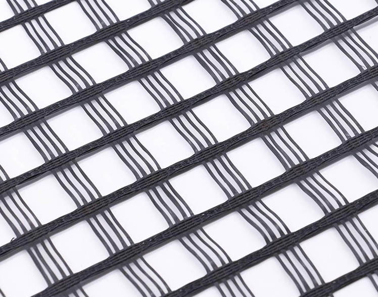
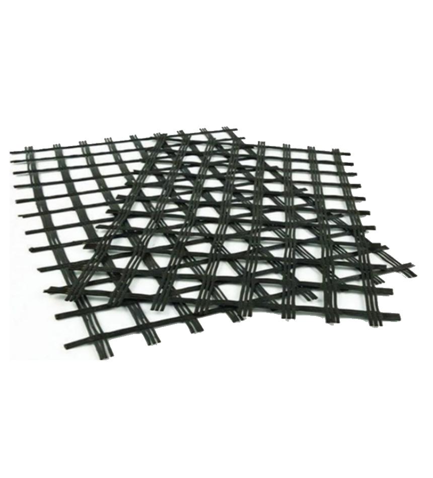
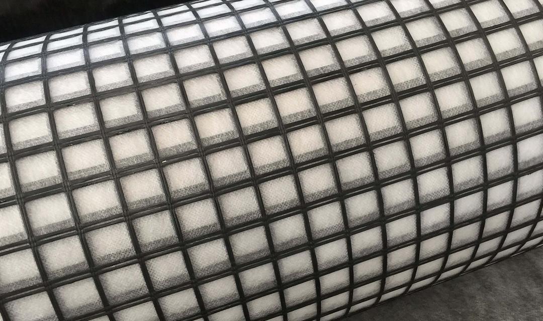
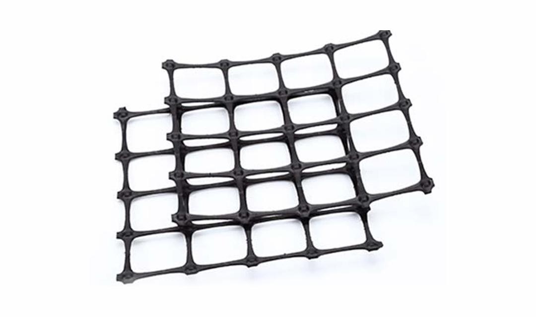
This product is a semi rigid product made of high-strength alkali free glass fiber and a mesh substrate made through internationally advanced warp knitting technology, and coated with surface treatment. It has high tensile strength and low elongation in both warp and weft directions, and has excellent performances such as high temperature resistance, low cold resistance, aging resistance, corrosion resistance, etc. It is widely used in the reinforcement of asphalt pavement, cement pavement and subgrade, and engineering projects such as railway subgrade, embankment slope protection, airport runway, sand prevention and control.
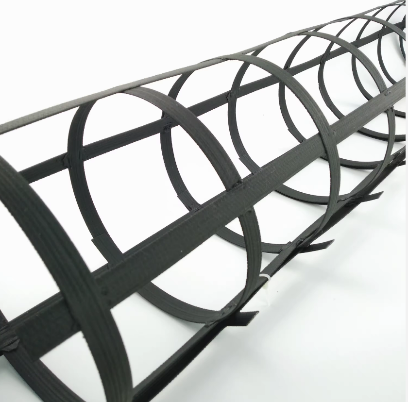
Width: 1-6 M
Material: fiberglass
Customization:
Width, tension, etc. can be customized according to customer requirements
Function:
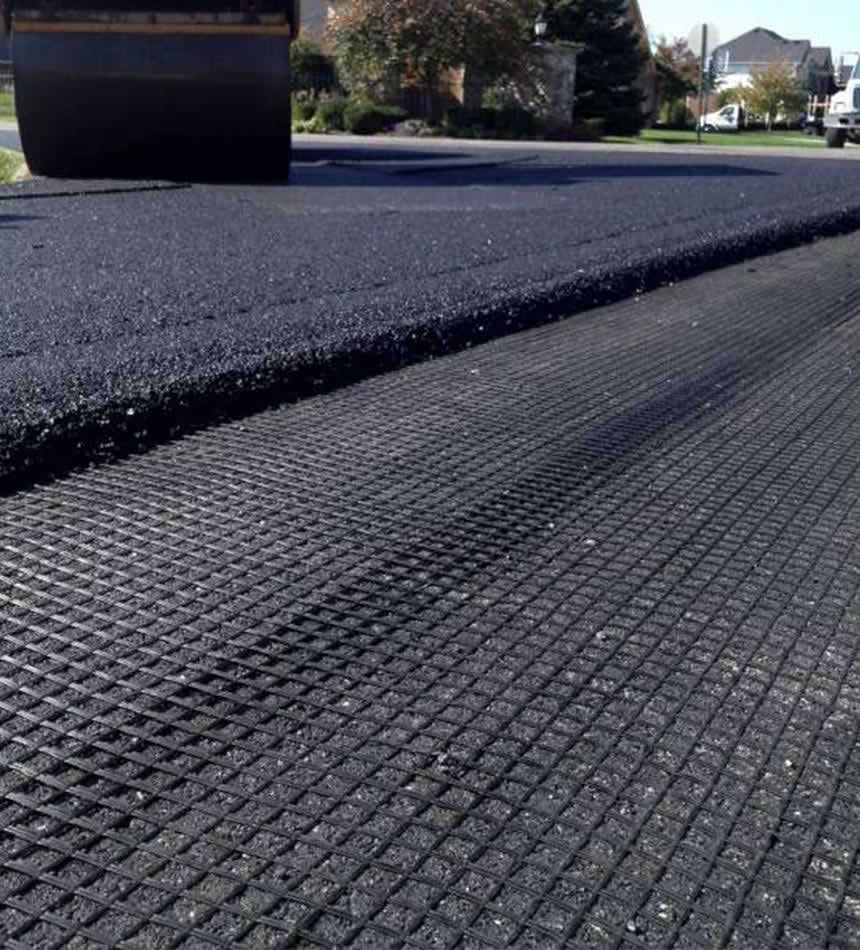
Old asphalt concrete pavement, cement concrete pavement reconstruction, composite pavement, road expansion and renovation engineering, soft soil foundation reinforcement treatment


| Specification Items | EGA30-30 | EGA50-50 | EGA60-60 | EGA80-80 | EGA100-100 | EGA120-120 | EGA150-150 | EGA200-200 | |
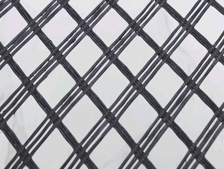
| Mesh center distance(mm) | 25.4x25.4 or 12.7x12.7 or set accordingly as required | ||||||||
Breaking strength ≥(kN/m) | Warp | 30 | 50 | 60 | 80 | 100 | 120 | 150 | 200 |
| Warp | 30 | 50 | 60 | 80 | 100 | 120 | 150 | 200 | |
Elongation at break ≤(%) | Warp | 4 | |||||||
| Warp | 4 | ||||||||
| Temperature resistance(℃) | -100~280 | ||||||||
1. Old asphalt concrete pavement, reinforced with asphalt surface layer to prevent and control diseases.
2. The reconstruction of cement concrete pavement into a composite pavement caused reflection cracks due to plate shrinkage.
3. Road expansion and renovation engineering to prevent cracks caused by uneven settlement at the junction of new and old roads.
4. The reinforcement treatment of soft soil foundation is conducive to the consolidation of soft soil, effective settlement, uniform stress distribution, and enhanced overall strength of the roadbed.
5. Shrinkage cracks occur in the semi rigid base of newly constructed roads, and reinforcement is added to prevent pavement cracks caused by reflection of foundation cracks.


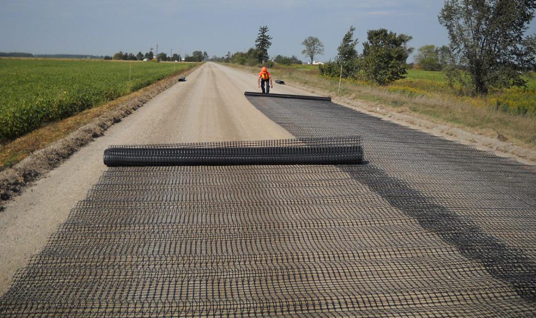
The commonly used fiberglass geogrids have two types: with and without self-adhesive adhesive. Those with self-adhesive adhesive can be directly laid on the leveled base layer, while those without self-adhesive adhesive are usually fixed with nails.
1. Construction site: It is required to be compacted, flat, horizontal, and remove sharp protrusions.
2. Grid laying: On a flat and compacted site, the main force direction (longitudinal) of the installed grid should be perpendicular to the axis of the embankment, and the laying should be flat, without wrinkles, and as tight as possible. Fixed by inserting nails and earth and stone weights, the main direction of force on the laid grid should be the full length without joints. The connection between the amplitudes can be manually tied and overlapped, with a width of no less than 10cm. If the grid is set up in more than two layers, the gaps between layers should be staggered. After laying a large area, the overall flatness should be adjusted. After filling a layer of soil and before rolling, the grid should be tensioned again using manual or machine tools, with even force, so that the grid is in a straight and stressed state in the soil.
3. Selection of fillers: Fillers should be selected according to design requirements. Practice has proven that except for frozen soil, swamp soil, household waste, chalk soil, and diatomaceous earth, they can all be used as fillers. However, gravel soil and sand soil have stable mechanical properties and are less affected by water content, so they should be selected first. The particle size of the filler shall not exceed 15cm, and attention shall be paid to controlling the grading of the filler to ensure the compaction weight.
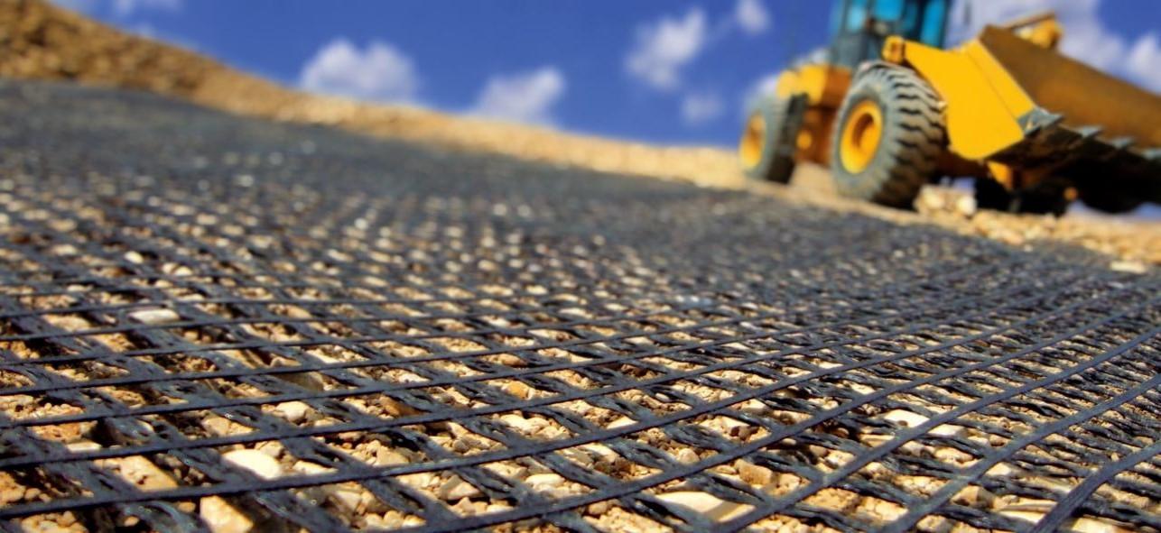
4. Spreading and compaction of filling materials: After the grid is laid and positioned, it should be covered with soil in a timely manner. The exposure time should not exceed 48 hours, and a flow process method of backfilling while laying can also be adopted. First spread the filler at both ends, fix the grille, and then push it towards the middle. The sequence of rolling is from both sides first to the middle. During rolling, the roller should not directly come into contact with the reinforcement material, and vehicles are generally not allowed to drive on the uncompacted reinforcement body to avoid misalignment of the reinforcement material. The compaction degree of each layer is 20-30cm. The compactness must meet the design requirements, which is also the key to the success or failure of reinforced soil engineering.
5. Waterproof and drainage measures: In reinforced soil engineering, it is necessary to ensure proper drainage treatment inside and outside the wall; To protect feet and prevent erosion; Filter and drainage measures should be installed inside the soil, and if necessary, geotextile should be installed.
Previous : First
Next:Uniaxial Geogrid

Boyuan Geosynthetics provides perfect environmental protection slope protection, greening and soil stabilization system solutions for global customers in large-scale civil engineering projects such as highway and railroad transportation, water conservancy construction, landscaping, bridges and tunnels.


Hot Keywords:GeocellGeogridGeotexileGeocompositeGeomatGeomembrance